| MECHANICAL RELEASE MECHANISM – MRM | ||
| MRM Control Panel | Detector Components | Detector Network |
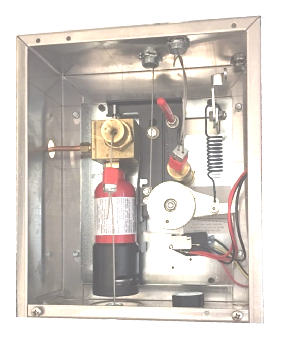
| ▪ Detection using Fusible Links ▪ Separate Manual Pull, ▪ Detection Line, and Gas Shut Off ▪ Two switches Installed at Factory, can accommodate up to 4 ▪ Actuate 1 to 10 cyl 275 – 375 – 475 or 1 to 6 MODEL 600 Cylinders or Mix 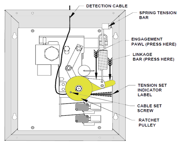 |
Detector Assembly Link Holder Test Link shown PN12891 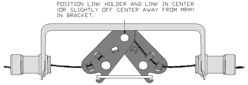 PN12327 – 280° 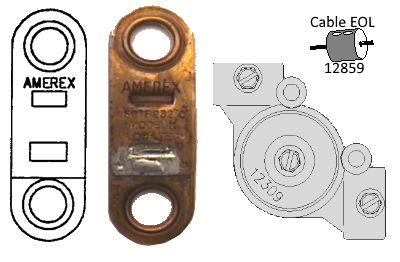 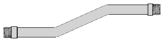 |
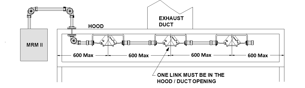
LINEAR NETWORK OF SPOT DETECTORS ▪ Maximum of 30 corner pulleys ▪ Maximum of 30 detectors ▪ Maximum of 200 feet of cable in the detection network ▪ No Tee Pulleys are allowed ▪ Remote manual pulls are not allowed on the detection network ▪ Maximum of 1 conduit offset (only at MRM) ▪ Position link holder and link in the center of the bracket or off center away from the MRM ▪ With tension bar in the down position, remove all slack from the cable ▪ Thread cable through “key” and attach to the appropriate slot on the link plate ▪ A gap (approx. 3 – 6mm) should be present between the trip post on the back of the link plate and the collapsible columns in the MRM when the tension lever is up and the MRM is cocked
|
| PNEUMATIC RELEASE MECHANISM – PRM | ||
| PRM Control Panel | Detector Components | Detector Network |
| ▪ Total Hood Detection ▪ Separate Manual Pull, ▪ Detection Line, and Gas Shut Off ▪ Two switches Installed at Factory, can accommodate up to 4 ▪ Actuate 1 to 10 cyl 275 – 375 – 475 or 1 to 6 MODEL 600 Cylinders or Mix  |
▪ Available in Bulk Length ▪ Cut to Fit – Easy to install ▪ Three Year Replacement Life ▪ One Temperature Works for All ▪ Actuation Temp. 435°F ▪ Install in areas where the maximum ambient temperature does not exceed 375°F. 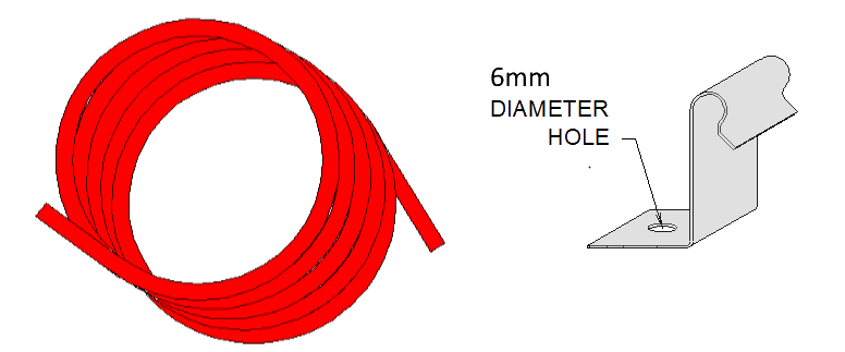 Bracket required every 450mm and within 25mm of the end of the line fitting. |
▪ Tubing should not interfere with any removable parts. ▪ Tubing must be secured with clip #16501 every 450mm ▪ Tubing must not be obscured by support structures. ▪ Do not route tubing in the path of hot flue gases. 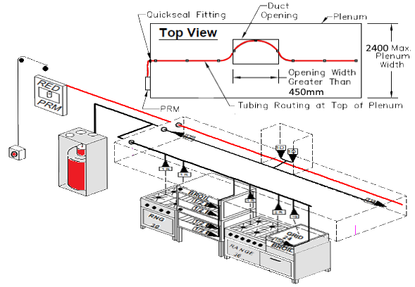 |
| AMEREX NITROGEN CYLINDER | |||
 |
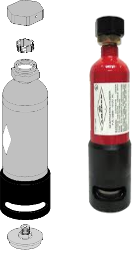 |
Amerex Nitrogen Actuation Cylinder • For use with the MRM or PRM One cartridge will actuate: • 10 Model KP275, 375, 475 Cylinders Or • 6 Model KP600 Cylinders Or • A Mix of 6 KP Cylinders containing at least one Model KP600 |
 |
| ACTUATION HOSE | |||||||||
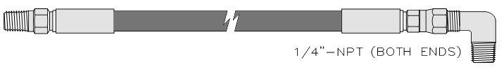
To aid in the installation of systems, an OPTIONAL actuation hose is available. This 400mm or 800mm hose connects the actuation port to the top of the cylinder discharge valve(s). P/N 12854 – 400mm P/N 16448 – 800mm |
|||||||||
| ACTUATION NETWORK | |||||||||
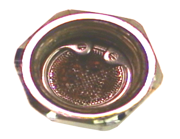
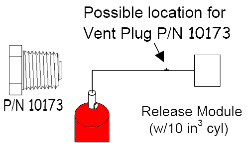 Amerex Vent Plug For Use in the Cylinder Actuation Line. • Prevents pressure build up in the actuation line due to temperature changes. • A required item |
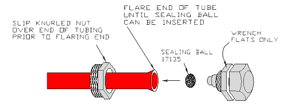
ACTUATION NETWORK LIMITATIONS – MRM OR PRM The actuation network for the Amerex Restaurant Fire Suppression System consists of factory supplied hose; installer supplied copper tubing or pipe that connects the MRM or PRM to each cylinder discharge valve. A single MRM or PRM is capable of actuating up to 10 x 2.75 / 3.75 / 4.75 gallon agent cylinder discharge valves or 6 x 6.14 gallon agent cylinder discharge valves by discharging a single 10 in3 nitrogen cylinder (P/N 12856) through the actuation network. If the network is a combination of any of the 2.75, 3.75 and or 4.75 with a 6.14 gallon cylinder, then maximum number of cylinders is six (6). Copper tubing – ¼” O.D. refrigeration type with a minimum wall thickness of .049 inches. Use with brass or steel compression style fittings (with brass or steel sleeves or ferrules). Max length (including all fittings) 30.0 m) High Pressure Hose – ¼” I.D. wire braid hose that is factory supplied. Max length (including all fittings) 16.46 m or a maximum number of 40 hose assemblies P/N 12854, 20 hose assemblies P/N 16448, or any combination that does not exceed a total 16.56 m. Pipe – ¼” NPT schedule 40 made of stainless steel, galvanized, chrome plated or black iron pipe: Max length 6.77m Maximum tees – 9 Maximum elbows – 9 (note: 2 – 45° elbows = 90°) Note: Different methods of constructing the actuation network may be mixed provided that the shortest limitations are followed, Example: A mix of ¼” copper tubing and ¼” high pressure hose requires that the hose limitations be followed (Max 16.46m) for the complete network. A mix of ¼” high pressure hose and ¼” pipe requires that the pipe limitations be followed (Max 6.77m) for the complete work. |
||||||||
| MANUAL PULL STATIONS | |||
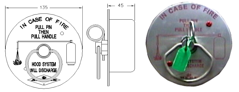 |
Amerex Manual Pull Station – 21481 • Remote Actuation – Mechanical, Cable Operated • Mounts in Standard 4” Oct. Conduit Box • Large Cover for Recessed Installation. • Double Action Actuation  |
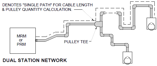 |
Manual Pull Network • Maximum of 130 feet of cable • One pulley tee per network • Maximum of 20 corner pulleys – either style • One conduit offset per network (must be located at the MRM) • Install manual pull stations no higher than 1200mm from floor. • Conduit must be secured at least every 900mm • Failure to properly secure conduit may cause to malfunction • Pull station requires only a travel of 20mm to operate • If tee pulley is used, set position of connector in the tee pulley should be farthest away from the pulley bearings |
| SWITCHES | ||
| WARNING: ELECTRICAL CONNECTIONS SHALL NOT BE MADE INSIDE THE MRM OR PRM ENCLOSURE. A SEPERATE LISTED ELECTRICAL JUNCTION BOX MUST BE USED. | ||
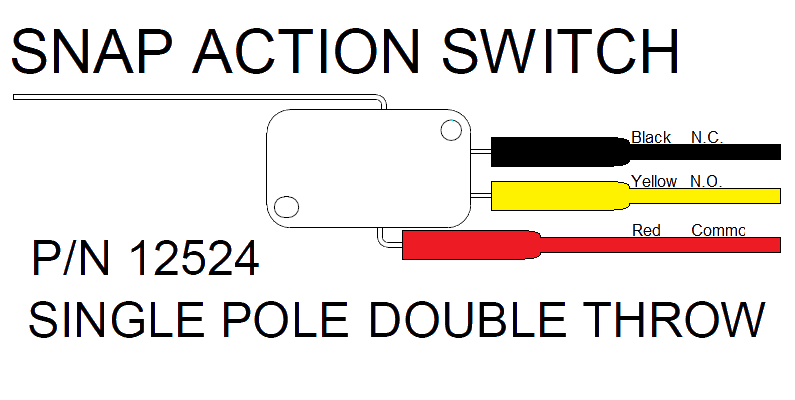
Field Install – Total 3 Equipment Shut Down |
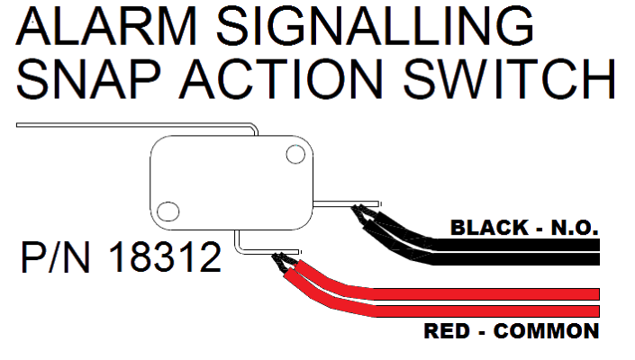
0.25A 30VDC – Alarm Initiation only |
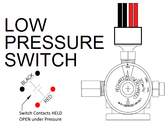
A low pressure switch is provided for connection to an alarm panel and/or the optional low pressure indicator. ONLY provided on PRM. |
| FLEXIBLE HOSE – HAZARD AREA | ||

This hose for use when a flexible movement of the nozzle branch line is desired. Such as when an appliance needs to be moved for cleaning and the nozzle protecting the appliance is fixed to the appliance. Hose length is 1200mm end to end and is supplied with ½” NPT ends. The flex hose is limited to use on the appliance branch line only and cannot be used on supply line or supply branch line. The flexible hose is to be connected to the Nozzle Branch line in a manner to prevent kinking or collapsing of the hose. It is to be used to provide for movement of the appliance without the appliance protection being disconnected from the fire suppression system. The flex hose has a minimum bend radius of 175mm. The flex hose takes the place of 1200mm of pipe. A maximum of three flex hoses may be used on an agent cylinder piping network. An appliance locating device is to be used to insure that the appliance is placed back in proper alignment after being moved for cleaning. NO RESTRAINT CABLE IS REQUIRED |
||
| AGENT DISTRIBUTION PIPING | |||
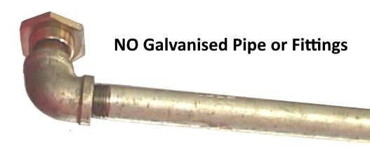 No galvanized pipe allowed ONLY Schedule 40, Black, Chrome Plated OR Stainless Steel PIPE can be used. |
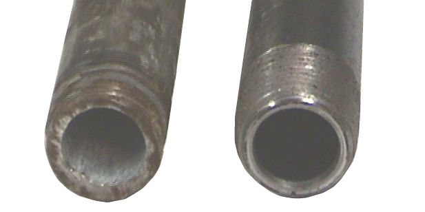 All pipe must be reamed and blown clear |
 Any dirt, cutting oil or shavings must be removed before assembly |
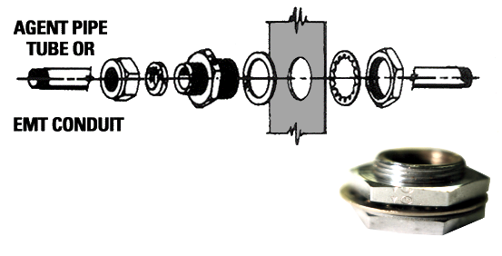 Hood Seal Adapters • Use for All External Hood Penetrations • Compression Type & Threaded • Liquid-Seal Type • UL Listed. |